Space Station receives first truss-mounted Wi-Fi® access point
NASA astronauts route first Ethernet cable onto truss and install a Wi-Fi® access point
Above the International Space Station’s habitable modules, the Integrated Truss Structure supports sun-tracking solar arrays, adjustable thermal radiator panels, experiment pallets, and transporter rails. The truss is packed with batteries, wiring, and coolant tubes. And the view is astounding.
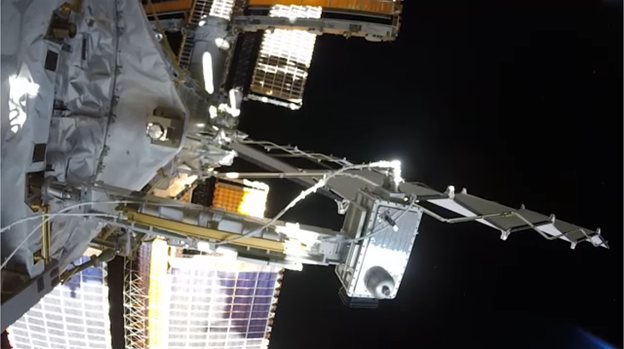
Figure 1: Closeout photograph of the International Space Station’s newest Wi-Fi access point. All of the infrastructure on the Space Station is Wi-Fi CERTIFIED™. Source: NASA
Floating above the Earth, astronaut Chris Cassidy carefully routed a total of 60m of Category 6 Ethernet cable onto the truss of the International Space Station. Chris wore a space suit and his hands worked against loose inflated glove fingers with layers of stiff protection. Unreeling a couple of meters from the spool in the canvas bag, Chris secured the cable to hand rails by twisting wire ties he pulled from pockets on the cable bag. Chris and his partner, Bob Behnken, had completed their task early: replacing old nickel-hydrogen batteries with new lithium ion batteries near the solar panels that power the outpost.
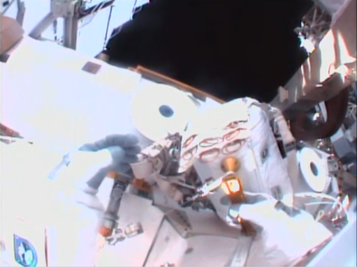
Figure 2: Helmet camera view as Chris Cassidy grasps the canvas Ethernet cable reel bag with wire tie pouch visible. Source: NASA
Two weeks later, on July 16, Cassidy returned to the station’s starboard truss carrying an access point (AP) packaged with a camera and pre-assembled with a pigtail cable onto a fixed boom. Chris installed the boom into a socket on the truss, assured himself it was captive and would not float away, then mated the power and Ethernet connections before proceeding past the solar panels to assist Behnken with exchanging more batteries.
The new AP Chris placed is on the aft face of the starboard truss, near the solar array rotary joint. From the vantage of the truss, it provides Wi-Fi coverage down to the modules. Presently, this is the only AP on the truss, aft of the truss, or peripherally starboard. The first APs had been mounted on the habitable pressurized modules, with the original intent of offering network connectivity from inside the modules out to payloads on the truss. The camera and boom had been on board and assembled since September 2019. Chris and Bob insisted on installing the camera before their primary task, so that the airlock would be empty if there were any emergency that required an early return.
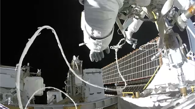
Figure 3: Chris Cassidy prepares to connect an Ethernet cable to a Wi-Fi access point on the starboard truss of the International Space Station. Source: NASA

Figure 4: First image from new Ethernet-connected camera, zoomed wide. A solar panel and a spare control-moment gyroscope are visible in the periphery. The camera shares an Ethernet cable with a Wi-Fi access point. Source: NASA
Part of a plan
This journey began in 2015. NASA had fully allocated the bandwidth of the first AP to upcoming science payload projects and future cameras before the first external client was installed. New science investigators and engineers proposing new payload and tool concepts also wanted to assume that Wi-Fi would be available for them.
Payloads were using heroic design approaches, like pointing high gain antennas and precisely analyzing signal power budgets. Projections for utilization of the first and second planned APs were showing that payloads would need to buffer their data and then coordinate and schedule their use of the wireless network.
The External Wireless team began to discuss “100% coverage.” In an ideating session in June, the team realized there were already plans to mount three APs on the truss. These access points were built into wireless cameras. The wireless cameras were a high-definition digital video upgrade with internally networked components, and so these APs were configured as wireless Ethernet bridges.
Suddenly, asking astronauts to fan a bundle of Ethernet cables to sites on the International Space Station’s truss, seemed like the logical thing to do. The External Wireless team developed a build-out plan that included the existing two and a third internally mounted APs using externally mounted antennas, ten Ethernet penetrations of the Space Station’s hull, five AP mounting locations on the truss with wired Ethernet, and a mounting location on the modules with wired Ethernet. That leaves four spare Ethernet penetrations, of which two have since been allocated to install Wi-Fi and video coverage in the docking corridor. There are now a total of 11 planned AP locations, and a couple of spare Ethernet cables on the outside of the Space Station.
There are so many potential installations that the new access point has been configured to reuse a frequency band already occupied by one of the APs with coverage forward of the station in the docking corridor. Support teams fabricated cables, cameras, and mounting hardware to support this concept. The crew is installing the components whenever they complete primary tasks early, and materials are staged to orbit incrementally, in anticipation of crew availability.
Retrofitting means meeting new requirements
The cameras are well-sited to be APs, but they were not designed for that purpose. The camera team had, however, provided an Ethernet test connector for themselves to use for development and testing on the ground. A person wearing gloves cannot reliably install or remove the test connector, and so engineers provided an Ethernet pigtail for the crew to install while in their living quarters.
Some cameras were to be mounted on pan and tilt assemblies, so the conversion from wireless to wired connectivity introduced the concern of binding and kinking. Several cable candidates were evaluated before a suitable product was found. Other cameras were mounted in fixed locations, but antenna pointing and camera pointing are coupled. In the case of this first truss AP, NASA prioritized Wi-Fi capability, and the antennas were pointed port and starboard to optimize coverage, constraining the camera angle to a plane from which the Imagery Group selected an Earth view.
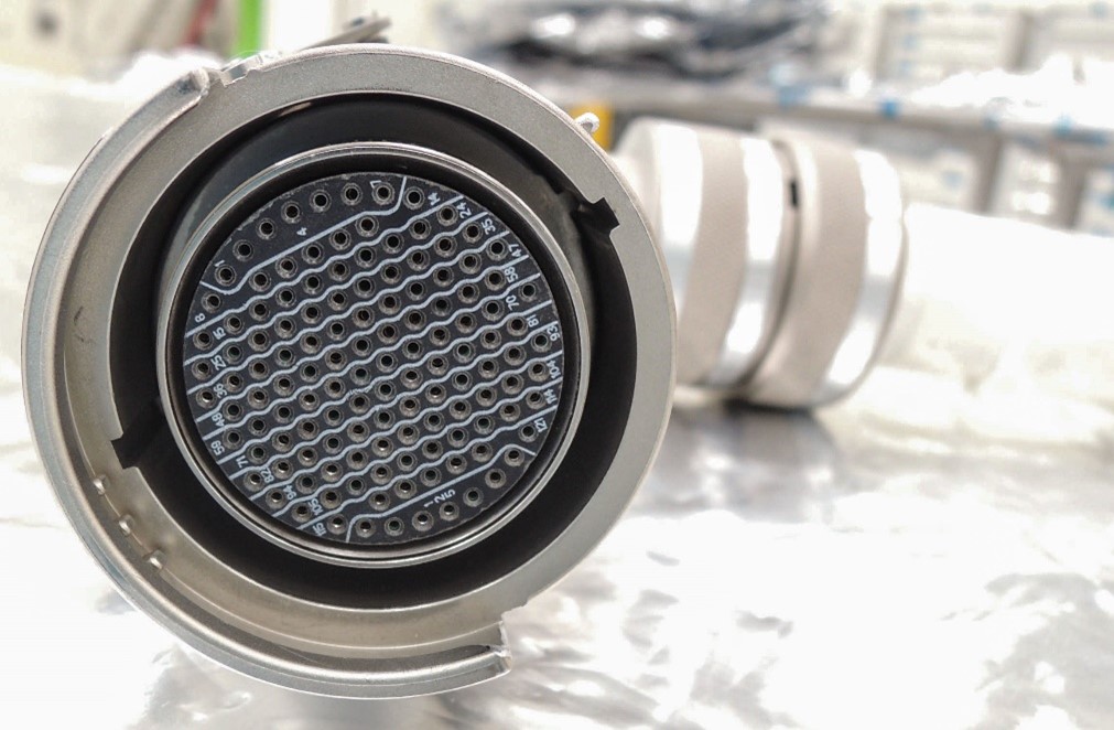
Figure 5: A connector on the flight external cable that breaks out ten Ethernet cables connected through the pressure wall of the International Space Station. Astronaut Ann McClain installed the zero-force multi-pin cable underneath a micrometeorite shield in April 2019. Source: NASA
Because NASA designed and fabricated modules during the 1990s, NASA had no penetrations through the pressure hull that meet Category 6 Ethernet requirements. Several Ethernet cables and other signals would need to penetrate the International Space Station’s vacuum-tight aluminum hull through a few zero-force multi-pin connectors. Engineers were very concerned about crosstalk and reflections among signal wire pairs at this connector stack, and Boeing conducted ground tests to develop confidence that gigabit speeds were achievable over the extension segment lengths concatenated by zero-gravity connectors.
A winning strategy
As the need arises or whenever crew availability allows, NASA continues to enlarge the coverage of the Wi-Fi infrastructure surrounding the International Space Station. The versatility of wireless network technology, interchangeable parts, and easily relocated installations, has allowed NASA’s External Wireless team to adapt quickly to meet emerging needs. Each new AP is increasing the capacity and robustness of the space community’s wireless network, thus expanding the kinds of applications that can choose Wi-Fi as a wireless data interface.
Trade names and trademarks are used in this report for identification only. Their usage does not constitute an official endorsement, either expressed or implied, by the National Aeronautics and Space Administration.
The statements and opinions by each Wi-Fi Alliance member and those providing comments are theirs alone, and do not reflect the opinions or views of Wi-Fi Alliance or any other member. Wi-Fi Alliance is not responsible for the accuracy of any of the information provided by any member in posting to or commenting on this blog. Concerns should be directed to info@wi-fi.org.
